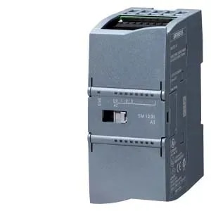
Description
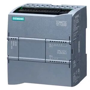
SIMATIC S7-1200, CPU 1211C, compact CPU, DC/DC/relay, onboard I/O: 6 DI 24 V DC; 4 DO relay 2 A; 2 AI 0-10 V DC, power supply: DC 20.4-28.8 V DC, program/data memory 75 KB
General information
Product type designation CPU 1211C DC/DC/relay
Firmware version V4.7
Engineering with
● Programming package STEP 7 V20 or higher
Supply voltage
Rated value (DC)
● 24 V DC Yes
permissible range, lower limit (DC) 20.4 V
permissible range, upper limit (DC) 28.8 V
Reverse polarity protection Yes
Load voltage L+
● Rated value (DC) 24 V
● permissible range, lower limit (DC) 20.4 V
● permissible range, upper limit (DC) 28.8 V
Input current
Current consumption (rated value) 300 mA; CPU only
Current consumption, max. 900 mA; CPU with all expansion modules
Inrush current, max. 12 A; at 28.8 V DC
I²t 0.8 A²·s
Output current
for backplane bus (5 V DC), max. 750 mA; Max. 5 V DC for CM
Encoder supply
24 V encoder supply
● 24 V L+ minus 4 V DC min.
Power loss
Power loss, typ. 8 W
Storage
Work memory
● Integrated 75 kbyte
Load memory
● Integrated 1 Mbyte
● Plug-in (SIMATIC Memory Card), max. with SIMATIC memory card
Backup
● present Yes
● maintenance-free Yes
● without battery Yes
CPU processing times
for bit operations, typ. 0.08 µs; / instruction
for word operations, typ. 1.7 µs; / instruction
for floating point arithmetic, typ. 2.3 µs; / instruction
CPU-blocks
Number of blocks (total) DBs, FCs, FBs, counters and timers. The maximum number of addressable blocks ranges from 1 to 65535. There is no restriction, the entire working memory can be used
OB
● Number, max. Limited only by RAM for code
Data areas and their retentivity
Retentive data area (incl. timers, counters, flags), max. 14 kbyte
Flag
● Size, max. 4 kbyte; Size of bit memory address area
Local data
● per priority class, max. 16 kbyte; Priority class 1 (program cycle): 16 KB, priority class 2 to 26: 6 KB
Address area
Process image
● Inputs, adjustable 1 kbyte
● Outputs, adjustable 1 kbyte
Hardware configuration
Number of modules per system, max. 3 communication modules, 1 signal board
● number of expansion boards (SB, CB, BB) 1
● number of signal modules (SM) 0
● number of communications modules (CM) 3
Time of day
Clock
● Hardware clock (real-time) Yes
● Backup time 480 h; Typical
● Deviation per day, max. ±60 s/month at 25 °C
Digital inputs
Number of digital inputs 6; Integrated
● of which inputs usable for technological functions 6; HSC (High Speed Counting)
Sourcing/sinking input Yes
Number of simultaneously controllable inputs
all mounting positions
— up to 40 °C, max. 6
Input voltage
● Rated value (DC) 24 V
● for signal “0” 5 V DC at 1 mA
● for signal “1” 15 V DC at 2.5 mA
Input current
● for signal “1”, typ. 4 mA; nominal
Input delay (for rated value of input voltage)
for standard inputs
— parameterizable 0.1 / 0.2 / 0.4 / 0.8 / 1.6 / 3.2 / 6.4 / 10.0 / 12.8 / 20.0 μs; 0.05 / 0.1 / 0.2 / 0.4 / 0.8 / 1.6 / 3.2 / 6.4 / 10.0 / 12.8 / 20.0 ms
— at “0” to “1”, min. 0.2 ms
— at “0” to “1”, max. 12.8 ms