Description
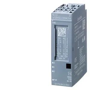
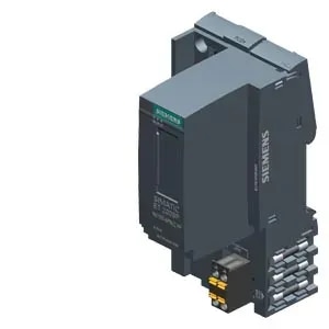
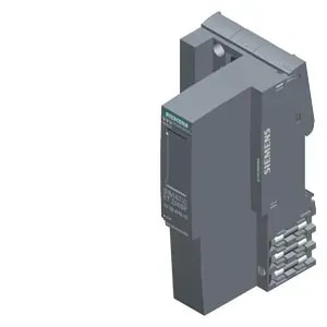
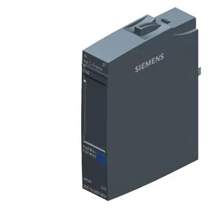
SIMATIC ET 200SP, ANALOG INPUT MODULE, AI 4XI 2-/4-WIRE STANDARD, PACKING UNIT: 1 PIECE, FITS TO BU-TYPE A0, A1, COLOR CODE CC03, MODULE DIAGNOSIS, 16BIT, +/-0,3%
General information
Product type designation AI 4xI 2-/4-wire ST
HW functional status From FS02
Firmware version
● FW update possible Yes
usable BaseUnits BU type A0, A1
Color code for module-specific color-coded label CC03
Product function
● I&M data Yes; I&M0 to I&M3
● Isochronous mode No
● Measuring range scalable No
Engineering with
● STEP 7 TIA Portal configurable/integrated from version V14 / -
● STEP 7 configurable/integrated from version V5.6 and higher
● PCS 7 configurable/integrated from version V8.1 SP1
● PROFIBUS from GSD version/GSD revision One GSD file each, Revision 3 and 5 and higher
● PROFINET from GSD version/GSD revision GSDML V2.3
Operating mode
● Oversampling No
● MSI No
CiR - Configuration in RUN
Reparameterization possible in RUN Yes
Calibration possible in RUN No
Supply voltage
Rated value (DC) 24 V
permissible range, lower limit (DC) 19.2 V
permissible range, upper limit (DC) 28.8 V
Reverse polarity protection Yes
Input current
Current consumption, max. 37 mA; without sensor supply
Encoder supply
24 V encoder supply
● 24 V Yes
● Short-circuit protection Yes
● Output current, max. 20 mA; max. 50 mA per channel for a duration < 10 s
Power loss
Power loss, typ. 0.85 W; Without encoder supply voltage
Address area
Address space per module
● Address space per module, max. 8 byte; + 1 byte for QI information
Hardware configuration
Automatic encoding Yes
● Mechanical coding element Yes
● Type of mechanical coding element Type A
Selection of BaseUnit for connection variants
● 2-wire connection BU type A0, A1
● 4-wire connection BU type A0, A1
Analog inputs
Number of analog inputs 4; Differential inputs
permissible input current for current input (destruction limit), max. 50 mA
Cycle time (all channels), min. Sum of the basic conversion times and additional processing times (depending on the parameterization of the active channels)
Input ranges (rated values), currents
● 0 to 20 mA Yes; 16 bit incl. sign
— Input resistance (0 to 20 mA) 100 Ω; + approx. 0.7 V diode forward voltage in 2-wire operation
● -20 mA to +20 mA Yes
— Input resistance (-20 mA to +20 mA) 100 Ω
● 4 mA to 20 mA Yes; 15 bit
— Input resistance (4 mA to 20 mA) 100 Ω; + approx. 0.7 V diode forward voltage in 2-wire operation
Cable length
● shielded, max. 1 000 m
Analog value generation for the inputs
Measurement principle integrating (Sigma-Delta)
Integration and conversion time/resolution per channel
● Resolution with overrange (bit including sign), max. 16 bit
● Integration time, parameterizable Yes
● Interference voltage suppression for interference frequency f1 in Hz 16.6 / 50 / 60 Hz
● Conversion time (per channel) 180 / 60 / 50 ms
Smoothing of measured values
● Number of smoothing levels 4; None; 4/8/16 times
● Parameterizable Yes
Encoder
Connection of signal encoders
● for voltage measurement No
● for current measurement as 2-wire transducer Yes
— Burden of 2-wire transmitter, max. 650 Ω
● for current measurement as 4-wire transducer Yes
Errors/accuracies
Linearity error (relative to input range), (+/-) 0.01 %
Temperature error (relative to input range), (+/-) 0.005 %/K
Crosstalk between the inputs, min. 50 dB; Applies to up to ±5 V overvoltage in other channels
Repeat accuracy in steady state at 25 °C (relative to input range), (+/-) 0.05 %
Operational error limit in overall temperature range
● Current, relative to input range, (+/-) 0.5 %
Basic error limit (operational limit at 25 °C)
● Current, relative to input range, (+/-) 0.3 %
Interference voltage suppression for f = n x (f1 +/- 1 %), f1 = interference frequency
● Series mode interference (peak value of interference < rated value of input range), min. 70 dB
● Common mode voltage, max. 10 V
● Common mode interference, min. 90 dB
Interrupts/diagnostics/status information
Diagnostics function Yes
Alarms
● Diagnostic alarm Yes
● Limit value alarm No
Diagnoses
● Monitoring the supply voltage Yes
● Wire break Yes; at 4 to 20 mA
● short-circuit Yes; 2-wire mode: Short-circuit of the encoder supply to ground or of an input to the encoder supply
● Group error Yes
● Overflow/Underflow Yes
Diagnostics indication LED
● Monitoring of the supply voltage (PWR-LED) Yes; green LED
● Channel status display Yes; green LED
● for channel diagnostics No
● for module diagnostics Yes; green/red LED
Potential separation
Potential separation channels
● between the channels Yes; channel group-specific between 2-wire current input group and 4-wire voltage input group
● between the channels and backplane bus Yes
● between the channels and the power supply of the electronics Yes; only for 4-wire transducer
Permissible potential difference
between the inputs (UCM) 10 V DC
Isolation
Isolation tested with 707 V DC (type test)
Standards, approvals, certificates
Ecological footprint
● environmental product declaration Yes
Global warming potential
— global warming potential, (total) [CO2 eq] 9.32 kg
— global warming potential, (during production) [CO2 eq] 4.97 kg
— global warming potential, (during operation) [CO2 eq] 4.79 kg
— global warming potential, (after end of life cycle) [CO2 eq] -0.449 kg
Specifications
| - | - |
|---|---|
| - | - |