Description
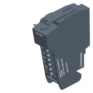
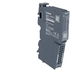
SIMATIC ET 200SP, Analog input module, AI 4xRTD/TC High Feature, suitable for BU type A0, A1, Color code CC00, channel diagnostics, 16 bit, +/-0.1%, 2-/3-/4-wire
Product type designation AI 4xRTD/TC 2-/3-/4-wire HF
HW functional status FS22 or higher
Firmware version V3.0.0
● FW update possible Yes
usable BaseUnits BU type A0, A1
Color code for module-specific color-coded label CC00
Product function
● I&M data Yes; I&M0 to I&M3
● Isochronous mode No
● Measuring range scalable Yes
Engineering with
● STEP 7 TIA Portal configurable/integrated from version V21 HSP0495 / integrated as of V21.1
● STEP 7 configurable/integrated from version V5.7 SP3 HF3 with HSP0348 V2.0 / integrated as of V5.8
● PCS 7 configurable/integrated from version V10.1
● PROFIBUS from GSD version/GSD revision One GSD file each, Revision 3 and 5 and higher
● PROFINET from GSD version/GSD revision GSDML V2.45
Operating mode
● Oversampling No
● MSI Yes
CiR - Configuration in RUN
Reparameterization possible in RUN Yes
Calibration possible in RUN Yes
Supply voltage
Rated value (DC) 24 V
permissible range, lower limit (DC) 19.2 V
permissible range, upper limit (DC) 28.8 V
Reverse polarity protection Yes
Input current
Current consumption (rated value) 34 mA
Current consumption, max. 35 mA
Power loss
Power loss, typ. 0.75 W
Address area
Address space per module
● Address space per module, max. 8 byte; + 1 byte for QI information
Hardware configuration
Automatic encoding Yes
● Mechanical coding element Yes
● Type of mechanical coding element Type A
Selection of BaseUnit for connection variants
● 2-wire connection BU type A0, A1
● 3-wire connection BU type A0, A1
Analog inputs
Number of analog inputs 4
● For voltage measurement 4
permissible input voltage for voltage input (destruction limit), max. 30 V
Constant measurement current for resistance-type transmitter, typ. 0.7 mA; 1.7 mA for Cu10 sensors
Cycle time (all channels), min. Sum of the basic conversion times and additional processing times (depending on the parameterization of the active channels); for line compensation in case of a three-wire connection, an additional cycle is necessary
Technical unit for temperature measurement adjustable Yes; °C/°F/K
Input ranges (rated values), voltages
● -1 V to +1 V Yes; 16 bit incl. sign
— Input resistance (-1 V to +1 V) 1 MΩ
● -250 mV to +250 mV Yes; 16 bit incl. sign
— Input resistance (-250 mV to +250 mV) 1 MΩ
● -50 mV to +50 mV Yes; 16 bit incl. sign
— Input resistance (-50 mV to +50 mV) 1 MΩ
● -80 mV to +80 mV Yes; 16 bit incl. sign
— Input resistance (-80 mV to +80 mV) 1 MΩ
Input ranges (rated values), thermocouples
● type B Yes; 16 bit incl. sign
— Input resistance (Type B) 1 MΩ
● type C Yes; 16 bit incl. sign
— Input resistance (Type C) 1 MΩ
● Type E Yes; 16 bit incl. sign
— Input resistance (Type E) 1 MΩ
● Type J Yes; 16 bit incl. sign
— Input resistance (type J) 1 MΩ
● Type K Yes; 16 bit incl. sign
— Input resistance (Type K) 1 MΩ
● Type L Yes; 16 bit incl. sign
— Input resistance (Type L) 1 MΩ
● Type N Yes; 16 bit incl. sign
— Input resistance (Type N) 1 MΩ
● Type R Yes; 16 bit incl. sign
— Input resistance (Type R) 1 MΩ
● Type S Yes; 16 bit incl. sign
— Input resistance (Type S) 1 MΩ
● Type T Yes; 16 bit incl. sign
— Input resistance (Type T) 1 MΩ
● Type U Yes; 16 bit incl. sign
— Input resistance (Type U) 1 MΩ
● Type TXK/TXK(L) to GOST Yes; 16 bit incl. sign
— Input resistance (Type TXK/TXK(L) to GOST) 1 MΩ
Input ranges (rated values), resistance thermometer
● Cu 10 Yes; 16 bit incl. sign
— Input resistance (Cu 10) 1 MΩ
● Ni 100 Yes; 16 bit incl. sign
— Input resistance (Ni 100) 1 MΩ
● Ni 1000 Yes; 16 bit incl. sign
— Input resistance (Ni 1000) 1 MΩ
● LG-Ni 1000 Yes; 16 bit incl. sign
— Input resistance (LG-Ni 1000) 1 MΩ
● Ni 120 Yes; 16 bit incl. sign
— Input resistance (Ni 120) 1 MΩ
● Ni 200 Yes; 16 bit incl. sign
— Input resistance (Ni 200) 1 MΩ
● Ni 500 Yes; 16 bit incl. sign
— Input resistance (Ni 500) 1 MΩ
● Pt 100 Yes; 16 bit incl. sign
— Input resistance (Pt 100) 1 MΩ
● Pt 1000 Yes; 16 bit incl. sign
— Input resistance (Pt 1000) 1 MΩ
● Pt 200 Yes; 16 bit incl. sign
— Input resistance (Pt 200) 1 MΩ
● Pt 500 Yes; 16 bit incl. sign
— Input resistance (Pt 500) 1 MΩ
Input ranges (rated values), resistors
● 0 to 150 ohms Yes; 15 bit
— Input resistance (0 to 150 ohms) 1 MΩ
● 0 to 300 ohms Yes; 15 bit
— Input resistance (0 to 300 ohms) 1 MΩ
● 0 to 600 ohms Yes; 15 bit
— Input resistance (0 to 600 ohms) 1 MΩ
● 0 to 3000 ohms Yes; 15 bit
— Input resistance (0 to 3000 ohms) 1 MΩ
● 0 to 6000 ohms Yes; 15 bit
— Input resistance (0 to 6000 ohms) 1 MΩ
● PTC Yes; 15 bit
— Input resistance (PTC) 1 MΩ
Thermocouple (TC)
Temperature compensation
— Parameterizable Yes
— Reference channel of the module Yes
— internal comparison point Yes; with BaseUnit type A1
— Reference channel of the group Yes
— Number of reference channel groups 4; Group 0 to 3
— fixed reference temperature Yes
Cable length
● shielded, max. 200 m; 50 m with thermocouples
Analog value generation for the inputs
Measurement principle integrating (Sigma-Delta)
Integration and conversion time/resolution per channel
● Resolution with overrange (bit including sign), max. 16 bit
● Integration time, parameterizable Yes
● Basic conversion time, including integration time (ms)
— additional processing time for wire-break check 2 ms; In the ranges resistance thermometers, resistors and thermocouples
— additional power line wire-break check 2 ms; for 3/4 wire transducer (resistance thermometer and resistor)
● Interference voltage suppression for interference frequency f1 in Hz 16.6 / 50 / 60 Hz
● Conversion time (per channel) 180 / 60 / 50 / (67.5 / 22.5 / 18.75) ms
Smoothing of measured values
● Number of smoothing levels 4
● Parameterizable Yes
● Step: None Yes
● Step: low Yes; 4x smoothing
● Step: Medium Yes; 8x smoothing
● Step: High Yes; 16x conversion time
Encoder
Connection of signal encoders
● for voltage measurement Yes
● for resistance measurement with two-wire connection Yes
● for resistance measurement with three-wire connection Yes
● for resistance measurement with four-wire connection Yes
Errors/accuracies
Linearity error (relative to input range), (+/-) 0.01 %; ±0.1 % for resistance thermometers and resistance
Temperature error (relative to input range), (+/-) 0.0009 %/K; ±0.005 % / K at thermocouple
Crosstalk between the inputs, min. -50 dB
Repeat accuracy in steady state at 25 °C (relative to input range), (+/-) 0.05 %
Operational error limit in overall temperature range
● Voltage, relative to input range, (+/-) 0.1 %
● Resistance, relative to input range, (+/-) 0.1 %
Basic error limit (operational limit at 25 °C)
● Voltage, relative to input range, (+/-) 0.05 %
● Resistance, relative to input range, (+/-) 0.05 %
Interference voltage suppression for f = n x (f1 +/- 1 %), f1 = interference frequency
● Series mode interference (peak value of interference < rated value of input range), min. 70 dB
● Common mode voltage, max. 10 V
● Common mode interference, min. 90 dB
Interrupts/diagnostics/status information
Diagnostics function Yes
Alarms
● Diagnostic alarm Yes
● Limit value alarm Yes; two upper and two lower limit values in each case
Diagnoses
● Monitoring the supply voltage Yes
● Wire break Yes; channel by channel
● short-circuit No
● Group error Yes
● Overflow/Underflow Yes; channel by channel
Diagnostics indication LED
● Monitoring of the supply voltage (PWR-LED) Yes; green PWR LED
● Channel status display Yes; green LED
● for channel diagnostics Yes; red LED
● for module diagnostics Yes; green/red DIAG LED
Potential separation
Potential separation channels
● between the channels No
● between the channels and backplane bus Yes
● between the channels and the power supply of the electronics Yes
Permissible potential difference
between the inputs (UCM) 10 V DC
Isolation
Isolation tested with 707 V DC (type test)
Standards, approvals, certificates
Ecological footprint
● environmental product declaration Yes
Global warming potential
— global warming potential, (total) [CO2 eq] 9.32 kg
— global warming potential, (during production) [CO2 eq] 4.97 kg
— global warming potential, (during operation) [CO2 eq] 4.79 kg
— global warming potential, (after end of life cycle) [CO2 eq] -0.449 kg