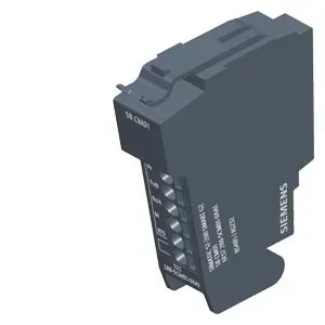
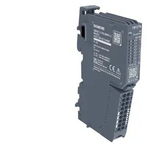
Description
SIMATIC ET 200SP, analog input module, AI Energy Meter CT ST, for 1A or 5A current transformer, suitable for BU type U0, channel diagnostics
General information
Product type designation AI Energy Meter CT ST
Firmware version V8.0
● FW update possible Yes
usable BaseUnits BU type U0
Color code for module-specific color-coded label CC20
Supported power supply systems TT, TN, IT
Product function
● Voltage measurement Yes
— without voltage transformer Yes
— with voltage transformer Yes
● Current measurement Yes; max. 3 + neutral conductor
— without current transformer No
— with current transformer Yes; 1 A or 5 A current transformer
— With Rogowski coil No
— With current-voltage-converter No
● Energy measurement Yes
● Frequency measurement Yes
● Power measurement Yes
● Active power measurement Yes
● Reactive power measurement Yes
● Power factor measurement Yes
● Active factor measurement Yes
● Reactive power compensation Yes
● Line analysis No
● I&M data Yes; I&M0 to I&M3
● Isochronous mode No
Engineering with
● STEP 7 TIA Portal configurable/integrated from version STEP 7 V16 or higher with HSP
● STEP 7 configurable/integrated from version Configurable via GSD file
● PROFIBUS from GSD version/GSD revision One GSD file each, Revision 3 and 5 and higher
● PROFINET from GSD version/GSD revision V2.3
Operating mode
● Switching between operating modes in RUN Yes; For module version 32 I/20 Q, it is possible to dynamically switch between 25 user data variants, 23 of which are pre-defined and 2 of which can be defined by the specific user
● Cyclic measured value access Yes
● Acyclic measured value access Yes
● Fixed measured value sets Yes
● Freely definable measured value sets Yes; For cyclic and acyclic measured value access
CiR - Configuration in RUN
Reparameterization possible in RUN Yes
Calibration possible in RUN Yes
Installation type/mounting
Mounting position any
Supply voltage
Rated value (DC) 24 V
permissible range, lower limit (DC) 19.2 V
permissible range, upper limit (DC) 28.8 V
Input current
Current consumption (rated value) 12.5 mA
Current consumption, max. 17 mA
Power loss
Power loss, typ. 1 W; 3x 5 A input current, 3x 230 V AC
Address area
Address space per module
● Inputs 256 byte
● Outputs 20 byte
Hardware configuration
Automatic encoding Yes
● Mechanical coding element Yes
● Type of mechanical coding element type C
Selection of BaseUnit for connection variants
● 2-wire connection BU type U0
Time of day
Operating hours counter
● present Yes
Analog inputs
Cycle time (all channels), typ. 50 ms; Time for consistent update of all measured and calculated values (cyclic und acyclic data)
Cable length
● shielded, max. 200 m
● unshielded, max. 200 m
Analog value generation for the inputs
Sampling frequency, max. 2 048 kHz
Interrupts/diagnostics/status information
Alarms
● Diagnostic alarm Yes
● Limit value alarm Yes
● Hardware interrupt Yes; Monitoring of up to 16 freely selectable process values (exceeding or undershooting of value)
Diagnoses
● Supply voltage Yes
● Hardware interrupt lost Yes
● Parameter assignment error Yes
● Module fault Yes
● Channel not available Yes
● Overflow/Underflow Yes
● Overload current Yes
Diagnostics indication LED
● Monitoring of the supply voltage (PWR-LED) Yes
● Channel status display Yes; green LED
● for channel diagnostics Yes; red Fn LED
● for module diagnostics Yes; green/red DIAG LED
Integrated Functions
Measuring functions
● Measuring procedure for voltage measurement TRMS
● Measuring procedure for current measurement TRMS
● Type of measured value acquisition seamless
● Curve shape of voltage Sinusoidal or distorted
● Buffering of measured variables Yes
● Parameter length 128 byte
● Bandwidth of measured value acquisition 3.2 kHz; Harmonics: 63 / 50 Hz, 52 / 60 Hz
Measuring range
— Frequency measurement, min. 40 Hz
— Frequency measurement, max. 70 Hz
Measuring inputs for voltage
— Measurable line voltage between phase and neutral conductor 277 V
— Measurable line voltage between the line conductors 480 V
— Measurable line voltage between phase and neutral conductor, min. 3 V
— Measurable line voltage between phase and neutral conductor, max. 300 V
— Measurable line voltage between the line conductors, min. 6 V
— Measurable line voltage between the line conductors, max. 519 V
— Internal resistance line conductor and neutral conductor 1.5 MΩ
— Power consumption per phase 60 mW; 300 V AC
— Impulse voltage resistance 1,2/50µs 2.5 kV
— Measurement category for voltage measurement in accordance with IEC 61010-2-030 CAT II
Measuring inputs for current
— measurable relative current (AC), min. 1 %; Relative to measuring range; 1 A, 5 A
— measurable relative current (AC), max. 100 %; Relative to the secondary rated current 5 A
— Continuous current with AC, maximum permissible 5 A
— Apparent power consumption per phase for measuring range 5 A 0.6 VA
— Rated value short-time withstand current restricted to 1 s 100 A
— Input resistance measuring range 0 to 5 A 25 mΩ; At the terminal
— Surge strength 10 A; for 1 minute
— Zero point suppression 0 ... 20%, referred to the nominal current
Accuracy class according to IEC 61557-12
— Measured variable voltage 0,2
— Measured variable current 0,2
— Measured variable apparent power 0.5
— Measured variable active power 0.5
— Measured variable reactive power 1
— Measured variable power factor 0.5
— Measured variable active energy 0.5
— Measured variable reactive energy 1
— Measured variable neutral current 0,2
— Measured variable phase angle ±0.5 °; not covered by IEC 61557-12
— Measured variable frequency 0.05; only valid for the permissible voltage measuring range
Potential separation
Potential separation channels
● between the channels No
● between the channels and backplane bus Yes
● Between the channels and load voltage L+ Yes; Including FE
Isolation
Isolation tested with Between channels and backplane bus, 24 V supply: Routine test, 1 920 V AC, 2 s; between backplane bus and 24 V supply: Type test, 707 V DC
Standards, approvals, certificates
Ecological footprint
● environmental product declaration Yes
Global warming potential
— global warming potential, (total) [CO2 eq] 9.32 kg
— global warming potential, (during production) [CO2 eq] 4.97 kg
— global warming potential, (during operation) [CO2 eq] 4.79 kg
— global warming potential, (after end of life cycle) [CO2 eq]