Description
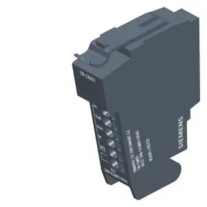
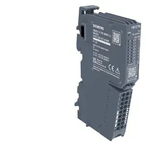
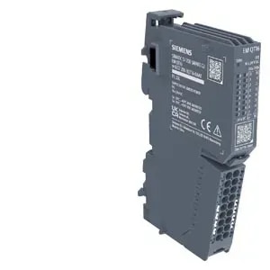
SIMATIC ET 200SP, digital input module, DI 8x NAMUR High Feature, suitable for BU type A0, Color code CC01, channel diagnostics
General information
Product type designation DI 8xNAMUR HF
HW functional status from FS21
Firmware version V2.0 or higher
● FW update possible Yes
usable BaseUnits BU type A0
Color code for module-specific color-coded label CC01
Product function
● I&M data Yes; I&M0 to I&M3
● Isochronous mode No
● suitable for operation on PROFINET R1 IMs Yes
Engineering with
● STEP 7 TIA Portal configurable/integrated from version V19
● STEP 7 configurable/integrated from version V5.5 SP3 / -
● PROFIBUS from GSD version/GSD revision GSD Revision 5
● PROFINET from GSD version/GSD revision GSDML V2.42
Operating mode
● DI Yes
● Counter Yes
● Oversampling No
● MSI No
Supply voltage
Rated value (DC) 24 V
permissible range, lower limit (DC) 19.2 V
permissible range, upper limit (DC) 28.8 V
Reverse polarity protection Yes
Input current
Current consumption, max. 70 mA
Encoder supply
Number of outputs 8
Short-circuit protection Yes
24 V encoder supply
● 24 V No
● Short-circuit protection No
NAMUR encoder supply
● 8.2 V Yes
● Short-circuit protection Yes
● Output current per channel, max. 8 mA
● Output current per module, max. 64 mA
Power loss
Power loss, typ. 1.5 W
Address area
Address space per module
● Address space per module, max. 1 byte
● Inputs 42 byte; 1 byte + 1 byte for QI information in DI mode; 42 bytes in Counter mode
● Outputs 20 byte; 0 in DI mode; 20 bytes in Counter mode
Hardware configuration
Automatic encoding Yes
● Mechanical coding element Yes
● Type of mechanical coding element Type A
Submodules
● Number of configurable submodules, max. 1
Selection of BaseUnit for connection variants
● 2-wire connection BU type A0
● 3-wire connection BU type A0
Digital inputs
Number of digital inputs 8; NAMUR
Digital inputs, parameterizable Yes
Sourcing/sinking input P-reading
Pulse extension Yes; 0.5 s, 1 s, 2 s
Edge evaluation Yes; rising edge, falling edge, edge change
Signal change flutter Yes; 2 to 32 signal changes
Flutter observation window Yes; 0.5 s, 1 s to 100 s in 1-s steps
Digital input functions, parameterizable
● Gate start/stop Yes
● Freely usable digital input Yes
● Counter Yes
— Number, max. 4; See manual for details
— Counting frequency, max. 5 kHz
— Counting width 32 bit
— Counting direction up/down Yes
Input voltage
● Rated value (DC) 8.2 V
Input current
for 10 k switched contact
— for signal “0”, min. 0.35 mA
— for signal “0”, max. 1.2 mA
— for signal “1”, min. 2.1 mA
— for signal “1”, max. 7 mA
for unswitched contact
— for signal “0”, max. (permissible quiescent current) 0.5 mA
— for signal “1”, typ. 8 mA
for NAMUR encoders
— for signal “0”, min. 0.35 mA
— for signal “0”, max. 1.2 mA
— for signal “1”, min. 2.1 mA
— for signal “1”, max. 7 mA
Input delay (for rated value of input voltage)
● tolerated changeover time for changeover contacts 300 ms
for standard inputs
— parameterizable No
for NAMUR inputs
— at “0” to “1”, max. 20 ms; See manual for details
— at “1” to “0”, max. 20 ms; See manual for details
Cable length
● shielded, max. 200 m; 50 m for Counter mode
Encoder
Connectable encoders
● NAMUR encoder/changeover contact according to EN 60947 Yes
● Single contact / changeover contact unconnected Yes
● Single contact / changeover contact connected with 10 kΩ Yes
Interrupts/diagnostics/status information
Diagnostics function Yes
Alarms
● Diagnostic alarm Yes; channel by channel
● Hardware interrupt Yes; Parameterizable, channels 0 to 7
Diagnoses
● Diagnostic information readable Yes
● Monitoring the supply voltage Yes
— parameterizable Yes
● Monitoring of encoder power supply No
● Wire break Yes; channel by channel
● Short-circuit Yes; channel by channel
Diagnostics indication LED
● Monitoring of the supply voltage (PWR-LED) Yes; green PWR LED
● Channel status display Yes; green LED
● for channel diagnostics Yes; red LED
● for module diagnostics Yes; green/red DIAG LED
Potential separation
Potential separation channels
● between the channels No
● between the channels and backplane bus Yes
● Between the channels and load voltage L+ Yes
● between the channels and the power supply of the electronics Yes
Isolation
Isolation tested with 707 V DC (type test)
Standards, approvals, certificates
Suitable for safety functions No
Ecological footprint
● environmental product declaration Yes
Global warming potential
— global warming potential, (total) [CO2 eq] 15.9 kg
— global warming potential, (during production) [CO2 eq] 3.69 kg
— global warming potential, (during operation) [CO2 eq] 12.7 kg
— global warming potential, (after end of life cycle) [CO2 eq] -0.495 kg
Ambient conditions
Ambient temperature during operation
● horizontal installation, min. -30 °C
● horizontal installation, max. 60 °C
● vertical installation, min. -30 °C
● vertical installation, max. 50 °C
Altitude during operation relating to sea level
● Installation altitude above sea level, max. 5 000 m; Restrictions for installation altitudes > 2 000 m, see manual
Absolute humidity
● dew point, min. -60 °C; suitable for dry room applications
Dimensions
Width 15 mm
Height 73 mm
Depth 58 mm
Weights
Weight, approx. 32 g